Pictured speaker grills in Freecad
October 5, 2024: Creating speaker grills with pictures as hole guide size
This is a continuation from a previous post on how to cut speaker grills in Freecad.
The last post ended with the expressed wish to use a picture as a template for a speaker grill.
This post now shows how to do this.
The solution
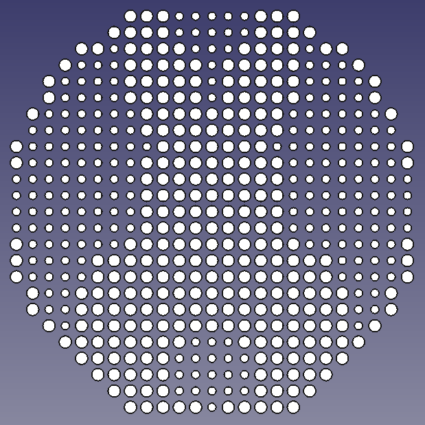
I once again used the Python console View->Panels->Python Console of Freecad to input a short script. This is the image we want to use as our template for the loudspeaker grill:

The script
Here is the script I This time around mostly Claude Sonnet 3.5 came up with.
It uses the pixel value (0=black, 255=white) of the image and adjusts the radius of circles spread over a configurable square size
visualize the image.
Pure black is ignored
import FreeCAD
import Part
from PIL import Image
import numpy as np

# Configuration
image_path = '/home/user/Pictures/bunnyais_grey.bmp'
grid_size_x = 5  # Grid size in cm
grid_size_y = 5  # Grid size in cm
hole_max_diameter = 0.15  # Maximum hole diameter in cm
hole_min_diameter = 0.1  # Minimum hole diameter in cm
hole_depth = 1  # Hole depth in cm
black_threshold = 10
grid_spacing = hole_max_diameter+0.05 #1mm spacing
pure_black_white = 0 # Change to 1 if you want to only have two circle sizes (min and max)

def load_and_prepare_image(image_path, grid_size_x, grid_size_y):
    img = Image.open(image_path).convert('L')
    img_array = np.array(img)

    # Calculate how many grid cells fit into the image dimensions
    grid_cells_x = int(np.ceil(img.width / (grid_size_x * 10)))  # Convert cm to mm
    grid_cells_y = int(np.ceil(img.height / (grid_size_y * 10)))  # Convert cm to mm
    grid_cells_x = int(np.ceil((grid_size_x/grid_spacing )))
    grid_cells_y = int(np.ceil((grid_size_y/grid_spacing )))
    print(f"x cells: {grid_cells_x}, y cells {grid_cells_y}")

    # If the grid cells are smaller than the image size, resize accordingly
    if grid_cells_x < 1 or grid_cells_y < 1:
        raise ValueError("Image is too small for the specified grid size.")
    img_resized = img.resize((grid_cells_x, grid_cells_y), Image.LANCZOS)

    return np.array(img_resized), grid_cells_x, grid_cells_y

def calculate_hole_diameter(pixel_value, max_diameter, min_diameter):
    if pixel_value < black_threshold:
      return 0
    if pure_black_white == 1:
      if pixel_value > 200:
        return min_diameter
      else:
        return max_diameter
    return min_diameter + (max_diameter - min_diameter) * (1 - pixel_value / 255)

def create_circle(x, y, diameter):
    return Part.Circle(FreeCAD.Vector(x, y, 0), FreeCAD.Vector(0, 0, 1), diameter / 2)

def process_image(image_array, grid_cells_x, grid_cells_y, grid_size_x, grid_size_y, max_diameter, min_diameter):
    circles = []
    for y in range(grid_cells_y):
        for x in range(grid_cells_x):
            pixel_value = image_array[y, x]
            hole_diameter = calculate_hole_diameter(pixel_value, max_diameter, min_diameter) * 10
            if hole_diameter == 0:
              continue

            # Calculate position in cm
            pos_x = x * grid_size_x/grid_cells_x * 10
            pos_y = (grid_cells_y - 1 - y) * (grid_size_y/grid_cells_y)  * 10 # Invert Y for FreeCAD
            print(f"pos x {pos_x} y {pos_y}")

            circles.append(create_circle(pos_x, pos_y, hole_diameter))
    return circles


def main():
    doc = FreeCAD.newDocument()

    # Load and prepare image
    image_array, grid_cells_x, grid_cells_y = load_and_prepare_image(image_path, grid_size_x, grid_size_y)

    # Process image and create circles
    circles = process_image(image_array, grid_cells_x, grid_cells_y, grid_size_x, grid_size_y, hole_max_diameter, hole_min_diameter)

    # Create shapes and extrude
    shapes = [circle.toShape() for circle in circles]
    for shape in shapes:
        obj = doc.addObject("Part::Feature", "Circle")
        obj.Shape = shape
        pad = doc.addObject("PartDesign::Pad", "Pad")
        pad.Profile = obj
        pad.Length = hole_depth * 10  # Convert cm to mm for FreeCAD

    doc.recompute()
    # Collect all extrusions (Assumes all extrusions are named 'Pad')
    extrusions = [obj for obj in doc.Objects if obj.TypeId == "PartDesign::Pad"]

    # Use Part.makeSolid() if needed to ensure all shapes are solids
    solid_shapes = [Part.makeSolid(ex.Shape) for ex in extrusions]

    # Fuse using Part Fuse operation
    fused_shape = solid_shapes[0]
    for shape in solid_shapes[1:]:
        fused_shape = fused_shape.fuse(shape)

    # Create a new object for the fused shape
    fused_object = doc.addObject("Part::Feature", "FusedObject")
    fused_object.Shape = fused_shape

    doc.recompute()

    return doc

if __name__ == "__main__":
    doc = main()
    FreeCADGui.activeDocument().activeView().viewAxometric()
    FreeCADGui.SendMsgToActiveView("ViewFit")
    FreeCADGui.updateGui()
Result
The script generates a fused shape
The fused shape can then be subtracted from another object. Go to “Part Design” Mode for this
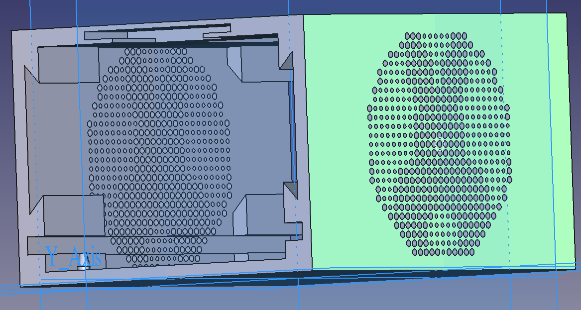
I had to play around a bit with the hole size and Grid spacing etc. until I achieved a result I was content with.